Stone HMI Display with Raspberry Pi
-
Table of Contents
[3] Software/ Tools Installation
[5] Working & Raspberry-Pi Coding
[1] Description
Stone Technologies is a professional Manufacturer of HMI Intelligent TFT LCD modules. Depending on the application the Stone Technologies offers Industrial Type, Advanced type, and Civil Type Intelligent TFT LCD modules available in different sizes. Visit Here .
In this project I am going to control LEDs with the help of this Stone HMI display. Command data, through Display will send to the Raspberry-pi and this data is in the form of frame because this Display sends data in the form of frame and receive in the frame of HEX code. Here I am using STWI056WT/N-01 model for our in this project, if you want to understand data frame and how it is working? you can download the Datasheet from here .
[2] Component List
[3] Software/ Tools Installation
before proceeding further we have to install Stone Designer and the Driver for USB so let see how to install these software. Below Drive link is given from that you can download the Designer tool and USB driver software.
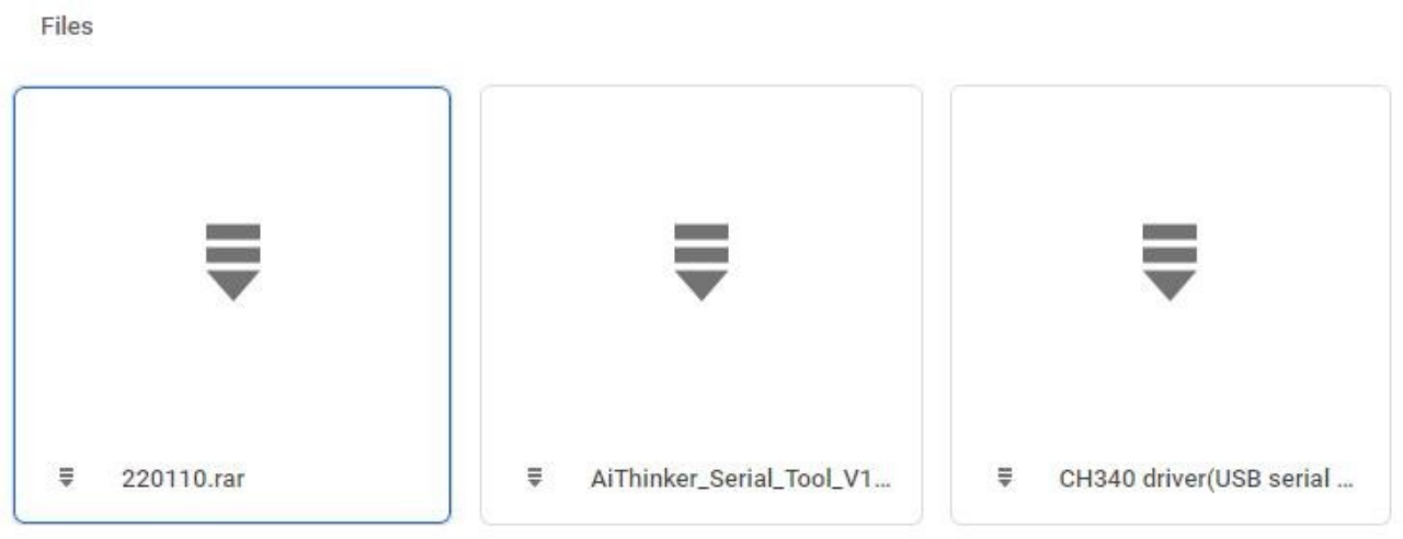
Step-1 :- Go to this Drive you will get a window as given below in the image and download these software and then install them in your computer.
Drive ink :- https://drive.google.com/drive/folders/1SbTuj9sqHLb9zV7pmEXOIyxWa9PAdOPH?usp=sharing
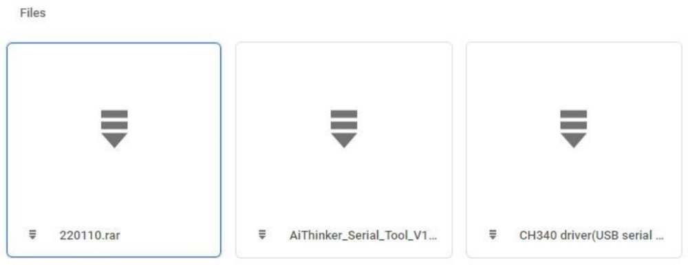 From here you have to download 1st and 3rd file, because first one is for GUI-Designer tool and 3rd is for USB driver.So download these software and let’s go for GUI design.
[4] GUI Designing & Uploading
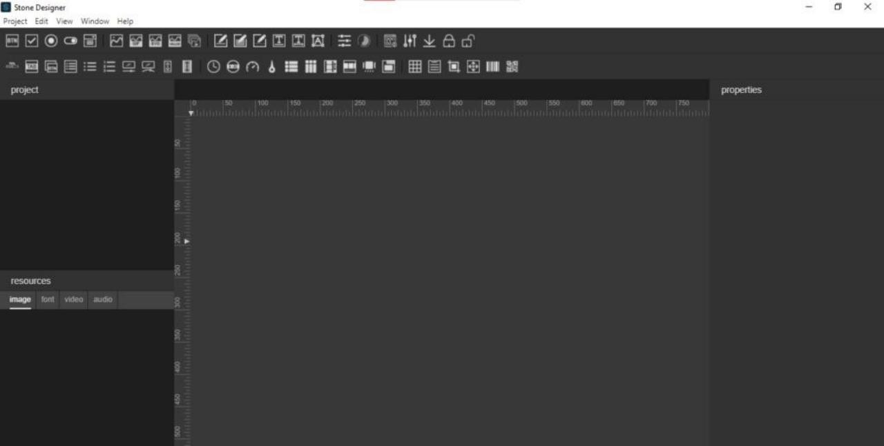
Let’s start first with interface designing. After installed , go to to Stone-Designer icon and click on that after that designer software will open and you will get this type of interface as shown in image.

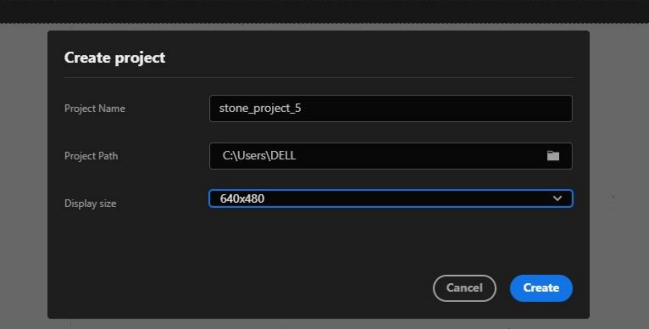
After opened you have to create a new project for this select ‘Project’ from top and from that select ‘new’ and you will ask for the some details as shown in the below figure , now give the name of project and select screen size as per your display size, here I’m using 640X480 size display , and select project path also after done with filling all the details click on ‘Create’ .

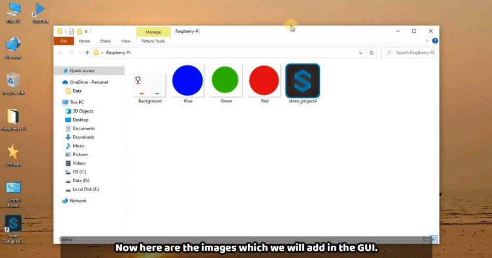
After done with above part select the background image for the project for this follow steps as shown in the figure.
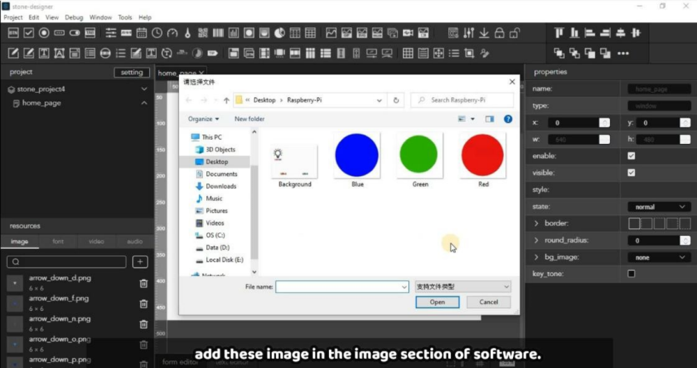
Step-1 :- Select ‘image’ from Resources to upload the image as back ground image and there are also other images which we will use for button purpose in further process, those images are given below, if you want you can design by your own.
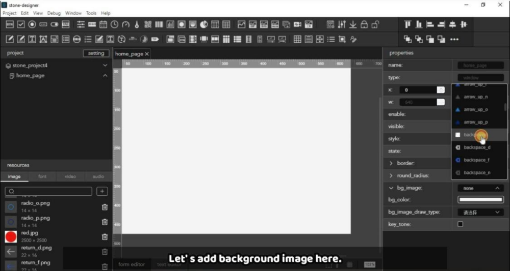
Step-2 :- Add these image in the GUI tool by clicking on that ‘+’ button as given in the below image.

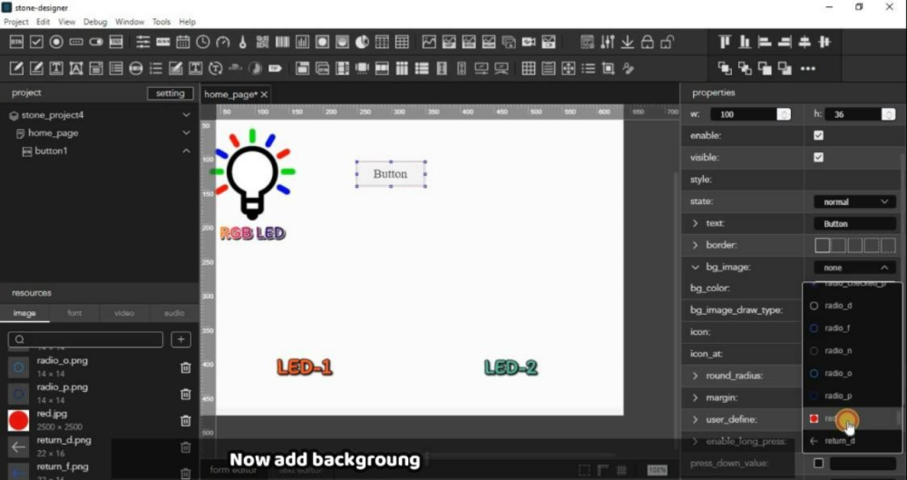
Step-3:- Now add first background image by clicking on blank screen and you will get more option in the right as shown in the image. From this select background image option and select that image which we have added just before this as per the below image.
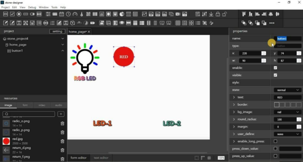
Step-4 :- Now add buttons for RGB one by one, you can see in the image one button is already added so first will apply changes in it and then similarly will do for other button.
Now select first button which we have added and go in properties of this which is in right side as given in image.

Step-4 :- From that select background image as Red image because this Button is for Red LED. And similarly do other settings like text color and size, so now we have done with first button, and you can follow same procedure for other buttons also.
But After added all the buttons you have to note down their name, which is highlighted in the below image. So you have to note for each button and you can give the name in the sequence like button1,button2.. and so on. This thing will require in the coding part, so keep it in your mind.
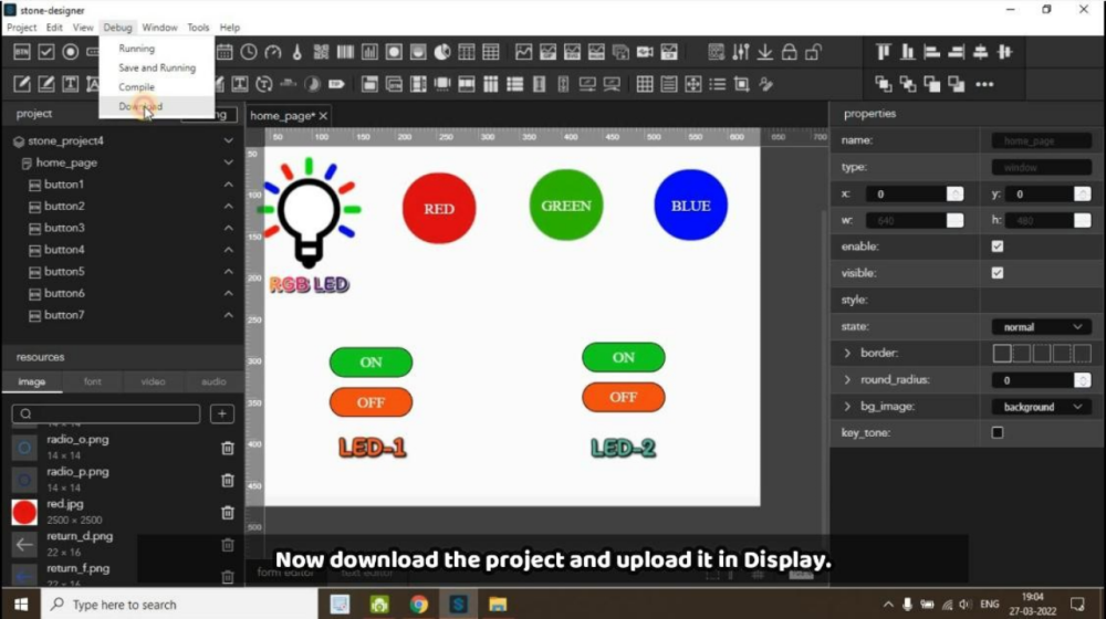
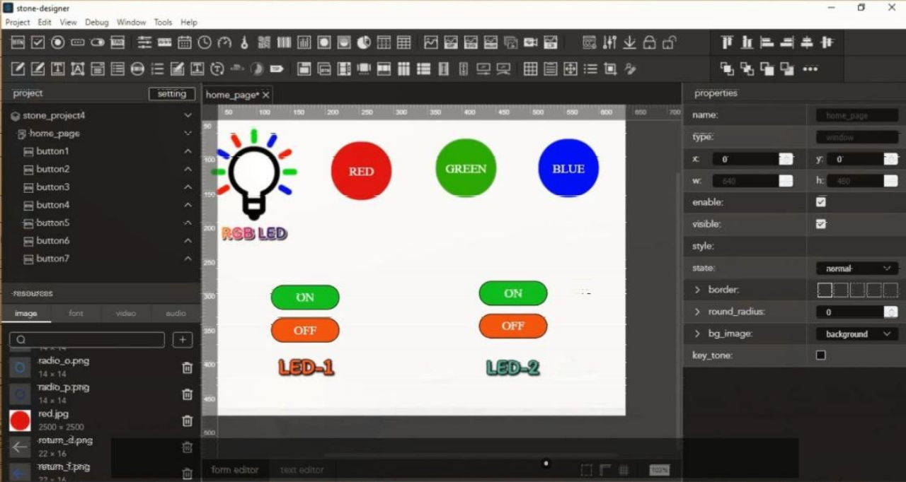
In this end it will look like this with all the buttons. So now GUI-Design is ready now we can proceed further.

Step-5 :- This step is for, to upload the GUI-Design in the display.For this first connect the display with power supply of 9-12 volt through power port. And then connect USB to USB to your PC with Display. It will look like this.

After connected the display now first we have to download the ‘Default’ folder through GUI-Tool. For this go to at Debug and click on Download then select the location where you want to download it.

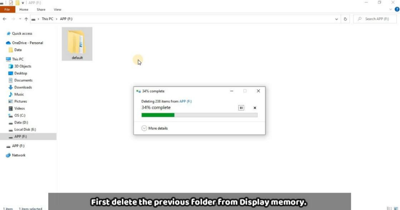
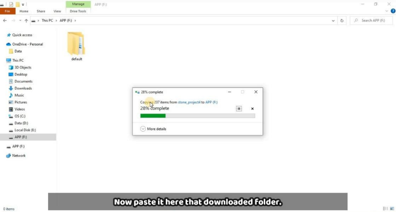
Now we have Default folder in our local machine will upload in the Display memory, for this first connect the display as mentioned above in the image through USB to USB communication with your PC. You will get a storage device in your PC there you have to delete first previous Default folder as mentioned in below image.

After that you can paste that folder here which we have copied from GUI design. As you can see in the below image.

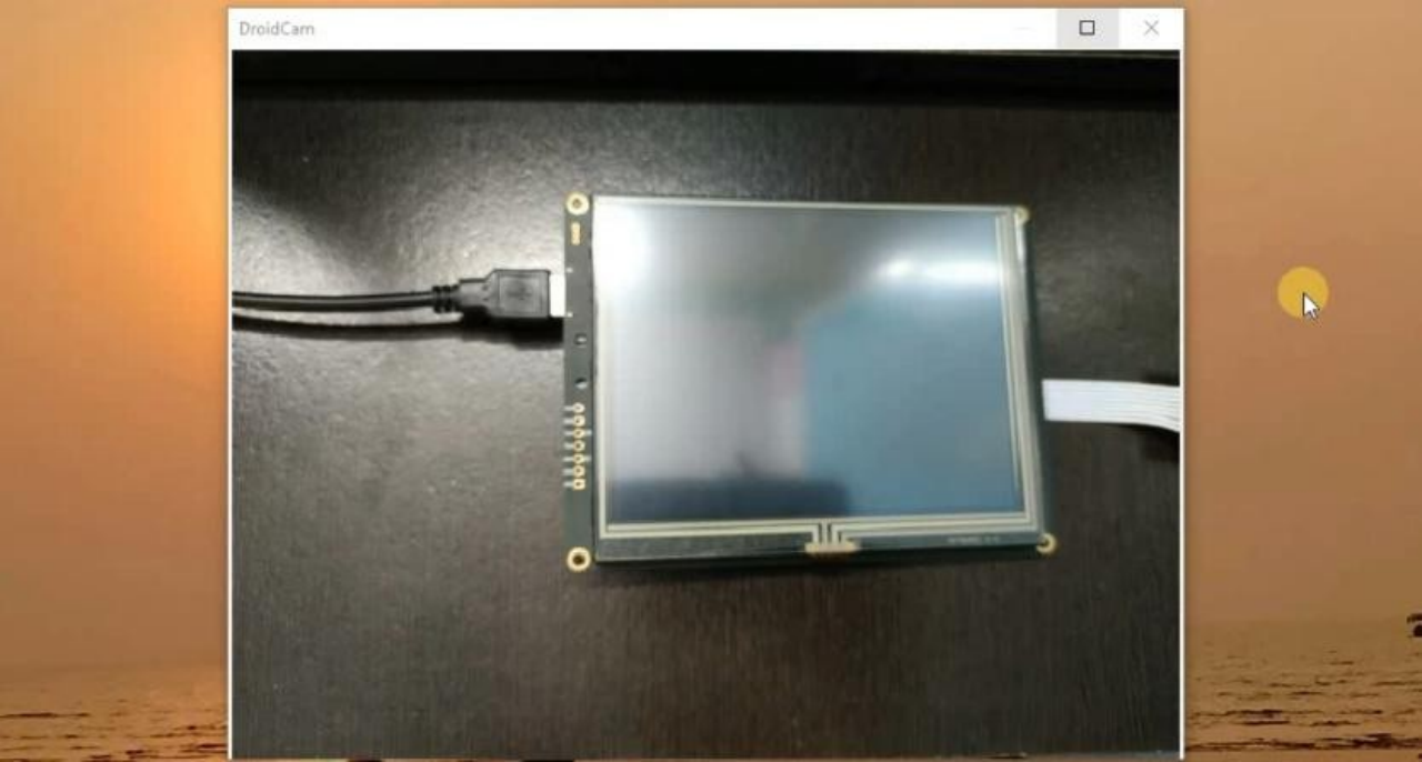
After pasted the default folder in display storage, just remove USB from Display and also remove the power supply, and after 2-3 sec just connect the power supply again to the display. Then you will get like this GUI which we have designed.
Now we have done with GUI design and uploading part , so its time to go through code and its working.
[5] Working & Raspberry-Pi Coding
Now first connect Raspberry-Pi through VNC server or you can connect directly through display as per your convenience. Then there are two codes which are given below. The first one is for testing the all buttons which we have created and second one the Whole code with I/O setup and it has logic.
Testing Code :-
serialcomm = serial.Serial('/dev/ttyUSB0', 115200) while True:
l=serialcomm.read(size=20) q=l[7:14]
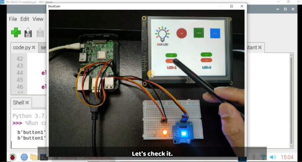
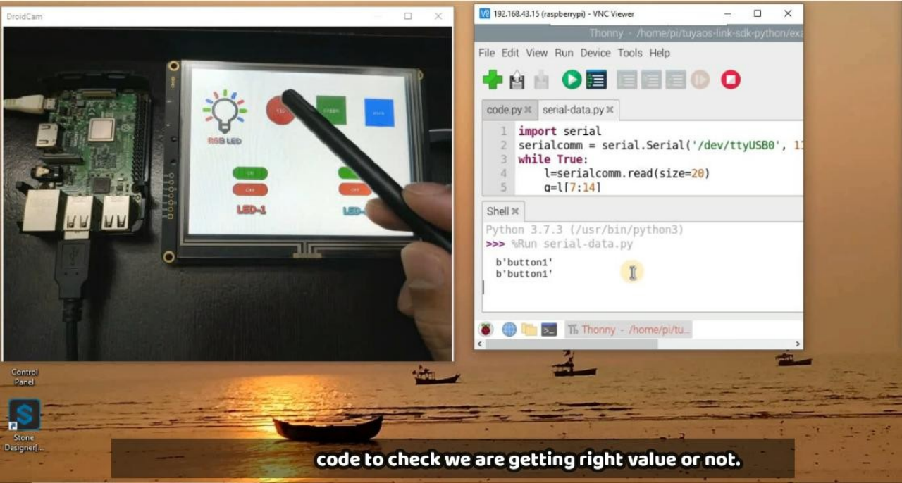
Here the purpose of testing code is to check all buttons so for this you need to connect first USB-0 of Raspberry-Pi to you Display TTL connector and then copy this code in Thonny of Raspberry-Pi as given in below image and then click on run button to test it.

By click any button which is on display will get a particular button name which we have assigned in the starting as we discussed it earlier. You can see after pressing Button-1 on display we are getting output string as button1 because we have done the slicing of whole from which we are getting from display.
l=serialcomm.read(size=20) q=l[7:14]
Here as in testing code these line of code, here l is variable which is receiving the frame from display size of 20, and then q is storing the sliced value as per our requirement.
And accordingly in complete code we made the logic as per individual button. Below logic is given as button6 will press then it will ON the LED2 high and if button7 will press it will of the LED2 as Off. Similarly all logic are working for others LEDs.
Complete Code :-
import RPi.GPIO as GPIO GPIO.setmode(GPIO.BCM) GPIO.setwarnings(False) led1 = 26
blue_led= 5 status1=0 status2=0
GPIO.setup(red_led,GPIO.OUT) GPIO.setup(green_led,GPIO.OUT) GPIO.setup(blue_led,GPIO.OUT) GPIO.setup(led1,GPIO.OUT) GPIO.setup(led2,GPIO.OUT) GPIO.output(red_led,GPIO.LOW) GPIO.output(green_led,GPIO.LOW) GPIO.output(blue_led,GPIO.LOW) GPIO.output(led1,GPIO.LOW) GPIO.output(led2,GPIO.LOW) ######################
while True: l=serialcomm.read(size=20) q=l[7:14]
GPIO.output(red_led,GPIO.HIGH) GPIO.output(green_led,GPIO.LOW) GPIO.output(blue_led,GPIO.LOW)
elif(q==b'button2'): GPIO.output(green_led,GPIO.HIGH) GPIO.output(red_led,GPIO.LOW) GPIO.output(blue_led,GPIO.LOW)
elif(q==b'button3'): GPIO.output(blue_led,GPIO.HIGH) GPIO.output(red_led,GPIO.LOW) GPIO.output(green_led,GPIO.LOW)
elif(q==b'button4'): GPIO.output(led1,GPIO.HIGH)
elif(q==b'button5'): GPIO.output(led1,GPIO.LOW)
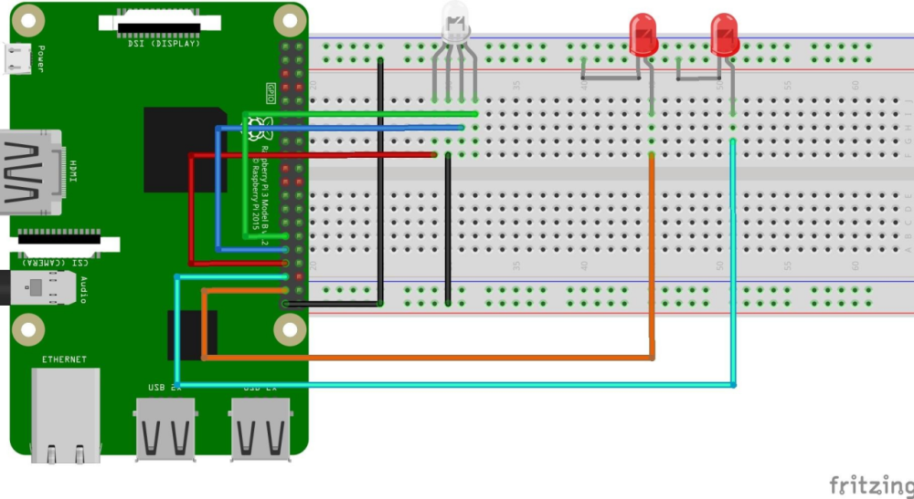
Now we have understand the logic behind the code let’s run the second code that is complete code in Raspberry-Pi but before this make the circuit connection like as given below in the circuit diagram.
Circuit Diagram :-
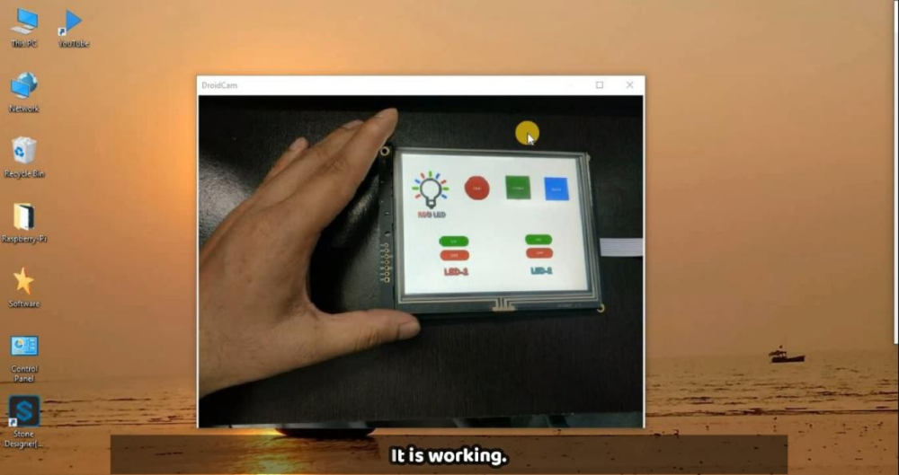
Now we have completed the whole project and the now you can test you project , the final setup will look like this.


-
Table of Contents
[3] Software/ Tools Installation
[5] Working & Raspberry-Pi Coding
[1] Description
Stone Technologies is a professional Manufacturer of HMI Intelligent TFT LCD modules. Depending on the application the Stone Technologies offers Industrial Type, Advanced type, and Civil Type Intelligent TFT LCD modules available in different sizes. Visit Here .
In this project I am going to control LEDs with the help of this Stone HMI display. Command data, through Display will send to the Raspberry-pi and this data is in the form of frame because this Display sends data in the form of frame and receive in the frame of HEX code. Here I am using STWI056WT/N-01 model for our in this project, if you want to understand data frame and how it is working? you can download the Datasheet from here .
[2] Component List
[3] Software/ Tools Installation
before proceeding further we have to install Stone Designer and the Driver for USB so let see how to install these software. Below Drive link is given from that you can download the Designer tool and USB driver software.
Step-1 :- Go to this Drive you will get a window as given below in the image and download these software and then install them in your computer.
Drive ink :- https://drive.google.com/drive/folders/1SbTuj9sqHLb9zV7pmEXOIyxWa9PAdOPH?usp=sharing
From here you have to download 1st and 3rd file, because first one is for GUI-Designer tool and 3rd is for USB driver.So download these software and let’s go for GUI design.
[4] GUI Designing & Uploading
Let’s start first with interface designing. After installed , go to to Stone-Designer icon and click on that after that designer software will open and you will get this type of interface as shown in image.
After opened you have to create a new project for this select ‘Project’ from top and from that select ‘new’ and you will ask for the some details as shown in the below figure , now give the name of project and select screen size as per your display size, here I’m using 640X480 size display , and select project path also after done with filling all the details click on ‘Create’ .
After done with above part select the background image for the project for this follow steps as shown in the figure.
Step-1 :- Select ‘image’ from Resources to upload the image as back ground image and there are also other images which we will use for button purpose in further process, those images are given below, if you want you can design by your own.
Step-2 :- Add these image in the GUI tool by clicking on that ‘+’ button as given in the below image.
Step-3:- Now add first background image by clicking on blank screen and you will get more option in the right as shown in the image. From this select background image option and select that image which we have added just before this as per the below image.
Step-4 :- Now add buttons for RGB one by one, you can see in the image one button is already added so first will apply changes in it and then similarly will do for other button.
Now select first button which we have added and go in properties of this which is in right side as given in image.
Step-4 :- From that select background image as Red image because this Button is for Red LED. And similarly do other settings like text color and size, so now we have done with first button, and you can follow same procedure for other buttons also.
But After added all the buttons you have to note down their name, which is highlighted in the below image. So you have to note for each button and you can give the name in the sequence like button1,button2.. and so on. This thing will require in the coding part, so keep it in your mind.
In this end it will look like this with all the buttons. So now GUI-Design is ready now we can proceed further.
Step-5 :- This step is for, to upload the GUI-Design in the display.For this first connect the display with power supply of 9-12 volt through power port. And then connect USB to USB to your PC with Display. It will look like this.
After connected the display now first we have to download the ‘Default’ folder through GUI-Tool. For this go to at Debug and click on Download then select the location where you want to download it.
Now we have Default folder in our local machine will upload in the Display memory, for this first connect the display as mentioned above in the image through USB to USB communication with your PC. You will get a storage device in your PC there you have to delete first previous Default folder as mentioned in below image.
After that you can paste that folder here which we have copied from GUI design. As you can see in the below image.
After pasted the default folder in display storage, just remove USB from Display and also remove the power supply, and after 2-3 sec just connect the power supply again to the display. Then you will get like this GUI which we have designed.
Now we have done with GUI design and uploading part , so its time to go through code and its working.
[5] Working & Raspberry-Pi Coding
Now first connect Raspberry-Pi through VNC server or you can connect directly through display as per your convenience. Then there are two codes which are given below. The first one is for testing the all buttons which we have created and second one the Whole code with I/O setup and it has logic.
Testing Code :-
serialcomm = serial.Serial('/dev/ttyUSB0', 115200) while True:
l=serialcomm.read(size=20) q=l[7:14]
Here the purpose of testing code is to check all buttons so for this you need to connect first USB-0 of Raspberry-Pi to you Display TTL connector and then copy this code in Thonny of Raspberry-Pi as given in below image and then click on run button to test it.
By click any button which is on display will get a particular button name which we have assigned in the starting as we discussed it earlier. You can see after pressing Button-1 on display we are getting output string as button1 because we have done the slicing of whole from which we are getting from display.
l=serialcomm.read(size=20) q=l[7:14]
Here as in testing code these line of code, here l is variable which is receiving the frame from display size of 20, and then q is storing the sliced value as per our requirement.
And accordingly in complete code we made the logic as per individual button. Below logic is given as button6 will press then it will ON the LED2 high and if button7 will press it will of the LED2 as Off. Similarly all logic are working for others LEDs.
Complete Code :-
import RPi.GPIO as GPIO GPIO.setmode(GPIO.BCM) GPIO.setwarnings(False) led1 = 26
blue_led= 5 status1=0 status2=0
GPIO.setup(red_led,GPIO.OUT) GPIO.setup(green_led,GPIO.OUT) GPIO.setup(blue_led,GPIO.OUT) GPIO.setup(led1,GPIO.OUT) GPIO.setup(led2,GPIO.OUT) GPIO.output(red_led,GPIO.LOW) GPIO.output(green_led,GPIO.LOW) GPIO.output(blue_led,GPIO.LOW) GPIO.output(led1,GPIO.LOW) GPIO.output(led2,GPIO.LOW) ######################
while True: l=serialcomm.read(size=20) q=l[7:14]
GPIO.output(red_led,GPIO.HIGH) GPIO.output(green_led,GPIO.LOW) GPIO.output(blue_led,GPIO.LOW)
elif(q==b'button2'): GPIO.output(green_led,GPIO.HIGH) GPIO.output(red_led,GPIO.LOW) GPIO.output(blue_led,GPIO.LOW)
elif(q==b'button3'): GPIO.output(blue_led,GPIO.HIGH) GPIO.output(red_led,GPIO.LOW) GPIO.output(green_led,GPIO.LOW)
elif(q==b'button4'): GPIO.output(led1,GPIO.HIGH)
elif(q==b'button5'): GPIO.output(led1,GPIO.LOW)
Now we have understand the logic behind the code let’s run the second code that is complete code in Raspberry-Pi but before this make the circuit connection like as given below in the circuit diagram.
Circuit Diagram :-
Now we have completed the whole project and the now you can test you project , the final setup will look like this.


Ciao! Sembra che tu sia interessato a questa conversazione, ma non hai ancora un account.
Stanco di dover scorrere gli stessi post a ogni visita? Quando registri un account, tornerai sempre esattamente dove eri rimasto e potrai scegliere di essere avvisato delle nuove risposte (tramite email o notifica push). Potrai anche salvare segnalibri e votare i post per mostrare il tuo apprezzamento agli altri membri della comunità.
Con il tuo contributo, questo post potrebbe essere ancora migliore 💗
Registrati Accedi